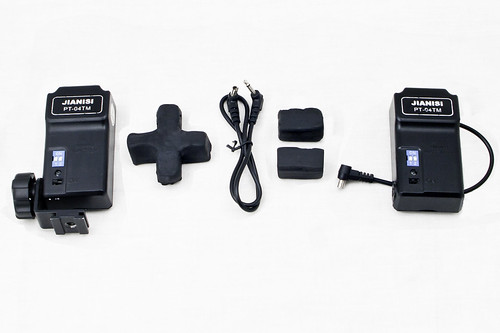
Since I originally only had a EX-430II flash, my first remote trigger was a Dealextreme bought PT-04. Since the EX-430II doesn't support external sync (shame on you canon!), the lack of a PC-sync out on the trigger was no big deal.
As my strobe collection expanded, and Light stands appeared in my inventory - I wanted in on the pc-jack goodness. Since I decided to stick with the PT-04's for compatibillity - my go-to solution was a soldering iron and a pair of wire cutters - shortly afterwards, my PT-04's had a pc sync-out.
If you haven't yet bought a remote yet, you might as well save yourself the trouble and get one that supports PC-Sync out of the box like these: AT-16, YN-04, and the nameless RF-Remote. Rumors are that even the latest PT-04's come with a PC-link. If you've already got a hotshoe-only remote, or are for solder happy and hell bent on going DIY - read on!
First of all, I must emphasis that doing this wrong (or even doing it right as far as I know) just might fry your precious 400$ strobe - so consider yourselves forewarned! I will not be held responsible for any fried strobes, or fried pets/people for that matter. Most strobes contain high-voltage capacitors, as far as I know this high voltage should never end up in the strobes outward-facing terminals - but again, I'm no expert - so be careful!
With that behind us - lets get to the fun stuff!
You'll need a PC-Cable (I'd recommend having at least a few spares), soldering iron, wire cutter/stripper, a small drill (even a manual one will do) and a multi-meter to test the connections.
The first thing you'll want to do, is open up your remote. If you'r lucky, you'll find two wires heading from the remotes PCB to its hotshoe. Make note which one connects to the central contact point, and which connects to the larger "shoe".
Next, cut of the 3.5mm end of the PC-Cable (the end you would normally plug into your camera) and strip that end of the wire. Strip the two internal cables as well.
 |
| click to enlarge |
I've found that while securing the cable in place, this knot sometimes breaks the wire within the PC-Cable - rendering it useless, so you might want to opt for some other method. Hot glue, for example, comes to mind.
Using the multi-tester, check which line leads to the PC-Cable's internal pin, and which leads to the external "circle". Now comes the tricky part - solder the wire that connects to the internal pin to the terminal corresponding to the hotshoe's inner "dot", then solder the second wire to the remaining terminal. Be sure not to leave any loose wires hanging around inside the remote - they could easily cause short-circuits (remember what I said about frying expensive strobes/beloved family members?).
I must admit that I found the correct connection configuration by accident. Connecting "center to center" seemed logical, and turned out to be right, I have no idea what would happen if I connected them the other way round. Any electrical-engineers/flash-experts in the crowd are welcome to weigh in on this.
To the left you can see the remote with a PC-Cable already knotted and soldered correctly. Before you close up - check conductivity between the PC-Cables terminals and the PCB, or even the remotes hotshoe. If everything checks out - close up, and your done!


